ABSTRACT
Ether is a word, which is not heard often. The word meaning of tether is ‘a rope or chain to fasten an animal so that it can graze within a certain limited area’. We can see animals like cows and goats ‘tethered’ to trees and posts.
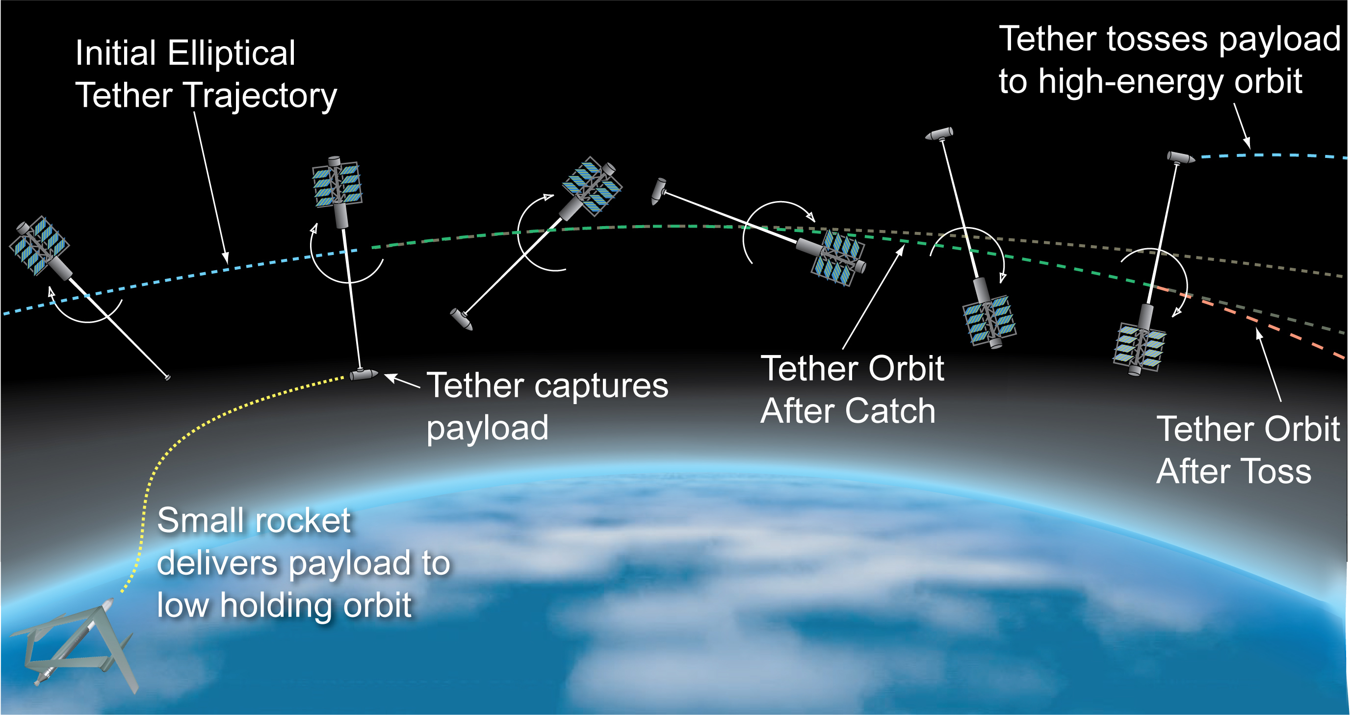
In space also tethers have an application similar to their word meaning. But instead of animals, there are spacecrafts and satellites in space. A tether if connected between two spacecrafts (one having smaller orbital altitude and the other at a larger orbital altitude) momentum exchange can take place between them. Then the tether is called momentum exchange space tether. A tether is deployed by pushing one object up or down from the other.
The gravitational and centrifugal forces balance each other at the center of mass. Then what happens is that the lower satellite, which orbits faster, tows its companion along like an orbital water skier. The outer satellite thereby gains momentum at the expense of the lower one, causing its orbit to expand and that of the lower to contract. This was the original use of tethers.
But now tethers are being made of electrically conducting materials like aluminium or copper and they provide additional advantages. Electrodynamic tethers, as they are called, can convert orbital energy into electrical energy. It works on the principle of electromagnetic induction.
This can be used for power generation. Also when the conductor moves through a magnetic field, charged particles experience an electromagnetic force perpendicular to both the direction of motion and field. This can be used for orbit raising and lowering and debris removal. Another application of tethers discussed here is artificial gravity inside spacecrafts.
Need of tethers
Space tethers have been studied theoretically since early in the 20th century, it wasn’t until 1974 that Guiseppe Colombo came up with the idea of using a long tether to support satellite from an orbiting platform. But that was simple momentum exchange space tether. Now lets see what made scientists think of electrodynamic tethers.
Every spacecraft on every mission has to carry all the energy sources required to get its job done, typically in the form of chemical propellants, photovoltaic arrays or nuclear reactors. The sole alternative – delivery service – can be very expensive. For example, a spacecraft orbiting in the International space Station (ISS) will need an estimated 77 metric tons of booster propellant over its anticipated 10 year life span just to keep itself from gradually falling out of orbit. Assuming a minimal price of $7000 a pound (dirt cheap by current standards) to get fuel up to the station’s 360 km altitude, i.e. $1.2 billion simply to maintain the orbital status quo.
So scientists have are taking a new look at space tether, making it electrically conductive. In 1996, NASA launched a shuttle to deploy a satellite on a tether to study the electrodynamic effects of a conducting tether as it passes through the earth’s magnetic fields. As predicted by the laws of electromagnetism, a current was produced in the tether as it passed through the earth’s magnetic field, acting as an electrical generator. This was the origin of electrodynamic tethers
Content
Electrodynamic tethers are thin, long conductive wires that are deployed in space which can be used to generate power by the use of kinetic energy from their orbital motion, or to produce thrust when we add an electrical energy from an on board source . In the other case the opposite thrust force is applied electrodynamically by the interaction of electric and magnetic fields. the most important pointed to be noted in this tether process is this electrodynamic tethering is only restricted to the celestial objects which consists of non-zero electric field and ionospheric plasma.
fundamental aspect of tether process is , when we look from a reference frame moving at some velocity v with respect to a fixed frame , an emf induced electric field will be generated ,
E’=E+v*B
where E and E’ are the electric fields in the stationary and moving frames and B represents the magnetic field. The orbital situation is depicted in the figure, where there is no electric field in the stationary frame, E’ = 0. From here, the induced EMF (Em) will be just the product of the magnitude of the velocity vector and the “horizontal” component of the magnetic field, Em = v*B*H. Assuming an elevation β of the magnetic field with respect to the horizontal, and a magnetic co-latitude of θm, we can write this field as, Em = v*B0* sin θm cos β, where B0 is the local magnitude of the magnetic field. Since in general the orbit will be inclined by an angle i, both the elevation and col-latitude will change and in consequence the magnitude of the Em field will change over time.
As an example of the magnitude of Em, consider a tether in a 300 km circular orbit. At this altitude, the orbital velocity is about 7700 m/s with a baseline field of B0 ∼ 2.6×10⁻⁵ Tesla. We then get Em ∼ v*B0 ≈ 200 V/km. If the tether is aligned in the direction of the field E ‘ , then a potential of Vm = 4 kV will be generated from end to end of a 20 km long tether. In principle, one could make use of this (non-constant) voltage source to generate power.
Tethers as Power Generators
In this case, we have a spacecraft deploying an insulated tether “upwards” as shown in the figure. We assume the tether moves with a velocity v under a perpendicular magnetic field BE . The tether has length e and a corresponding resistance RT .

As the tether moves, we have a field Em = vB that will generate an “open circuit” voltage Voc = vBl. If there is a load resistance RL in series, the a (positive) current will flow, as ionospheric electrons are collected on an exposed anode at the top of the tether,
I = Voc − ΔV /RT + RL
where ΔV is the (relatively small) total potential drop due to plasma sheaths at the anode and cathode. To complete the circuit, a cathode releases the electrons at the bottom of the tether. Given this current flow, electrical power will be generated at the load,
P = I*IRL = ( Voc − ΔV / RT + RL)* ( Voc − ΔV / RT + RL) *RL
We observe that the generated power is both zero when the load resistance is either zero or ∞. This means there is an optimum resistance that will yield maximum power. To find this, we differentiate the above equation and set it to zero, therefore,
Pmax = ( Voc − ΔV )* ( Voc − ΔV ) / 4RT * 4RT
which occurs when RL = RT
The efficiency of this power-generating tether can be defined as,
ηg =p/I*Voc =I*IRL/IVoc = 1 − RL/RT+RL(1- ΔV /Voc)
We can easily verify that for maximum power generation, the efficiency is ηg ≈ 0.5. Ideally, we would like RL » RT for maximum efficiency, but then we get lower power. We can also verify that the input power IVoc is identical to the rate of change of the electrodynamic drag work (force F, force density f ),
W˙ = F · v =integration of( f · v dV )= integration of(j × B.vdV = IBlv = IEml = IVoc
Tethers as Thrusters
Now, we have a spacecraft that deploys the tether “downwards”. In this case, the anode at the bottom collects electrons from the ionosphere. The Em field will point also upwards, however, we now have an on-board power supply that forces the net (positive) current in the opposite direction, as shown.

the efficiency of the tether as a thruster is,
ηt=W/IVs=IEmL/IVs=Voc/Vs<1
It is then possible to use a tether both as a generator and a propellant-less thruster. In fact, since the tether can be used as a generator, an interesting question would be: what is the tether efficiency compared against a fuel cell? Fuel cells make use of some consumable (like propellant) to produce electric power. As an exercise, calculate the efficiency of a tether producing power when its drag is compensated by a thruster consuming propellant. This is a tether working as a fuel cell.

Tether Dynamics
As we have seen, it is important that the tether is oriented along the radial vector in its orbit for it to be used as an electrodynamic generator or thruster. We need to analyze the tether dynamics to verify that such alignment can be achieved without the use of complicated active control. 4 Referring to the schematic, we have a mass-less tether of length l=l1+l2 with two point masses at its ends, such that m1 + m2 = m. Let us analyze the dynamics of m2, assuming that the center of mass (cm) is orbiting at a radius R. There will be a centrifugal force acting on m2 given by,
the projection of the force on the direction of the wire is the tension and is equal to
T=F cos θ
and the projection of the net force in the orthogonal direction generates a torque,
T’=-Fl sin θ and fro small θ ,T’=-3*m1*m2/m*(l*l*orbital velocity* θ )

The gravity gradient force gives a torque that goes in the opposite direction to the tether detection from the vertical and therefore it tends to stabilize the tether in the direction favourable for it use as an electrodynamic actuator, and the oscillation frequency of the tether is fw=sqrt(3*Orbital velocity).

SUMMARY
The use of EDT’s in the Jovian system, as shown in the artist’s concept (fig. 17), presents entirely new challenges and opportunities. In a circular orbit near the planet, it appears that induced tether voltage scan reach as high as 50,000 V, currents can become greater than 20 A, power levels can reach over a million watts, and propulsive forces can reach higher than 50 N. Utilizing this tremendous power is clearly beyond current engineering capabilities.They also appear to present significant engineering challenges including:
• High levels of tether current mean that managing a spacecraft system’s thermal budget is not simple
.• The complex geometry of forces that a tether would experience around Jupiter means that sophisticated control of tether current will be required in order to achieve specific mission orbital characteristics.
• The capture analysis illustrates the potential for reasonably sized tethers to generate significant propulsive forces and tremendous, megawatt-level power generation.

• The huge power levels predicted for the capture maneuver would require a relatively heavy tether system to handle the load. However, the weight of such a system could be justified for missions with very large power requirements.
• It also appears feasible that very short tethers (~1 km) could be utilized for generating substantial power and orbital maneuvering capabilities. Power generation via tether may provide arealistic alternative to RTG’s.
• The issue of tether stability remains open. Gravity gradient forces at Jupiter are insufficient to maintain tether orientation and tension under these propulsive loads. Alternative configurations, including a rotating system, should be considered.
• Additional analyses should be performed to evaluate the behavior of a tether system in lower altitude, more circular orbits. In these types of orbits it would be possible to provide continuous power and propulsive forces without the requirement to deal with the very large peak levels generated in highly elliptic orbits.


